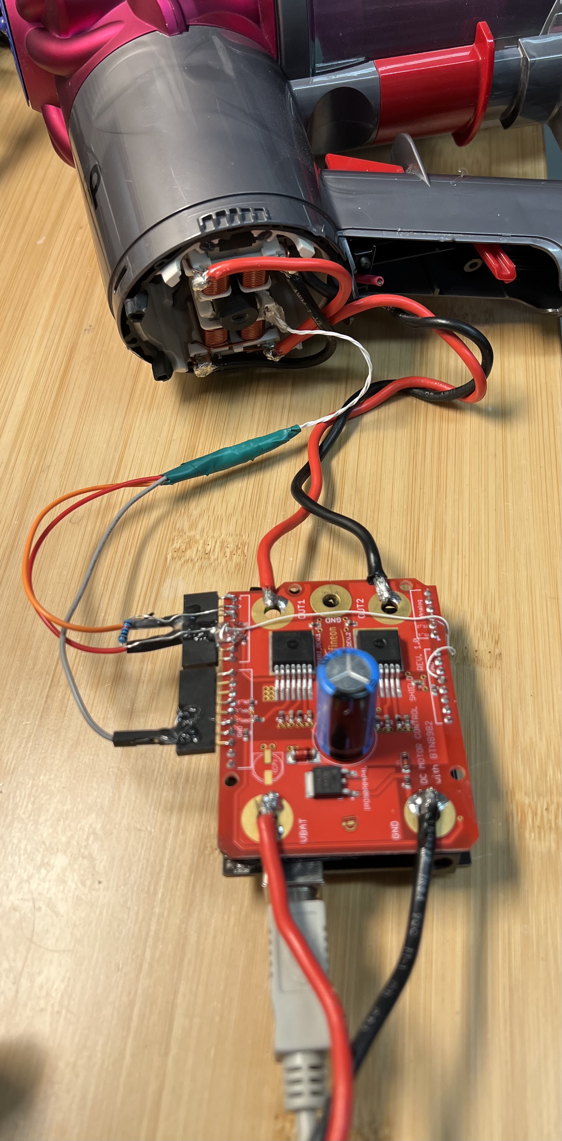
Dyson V6 Setup
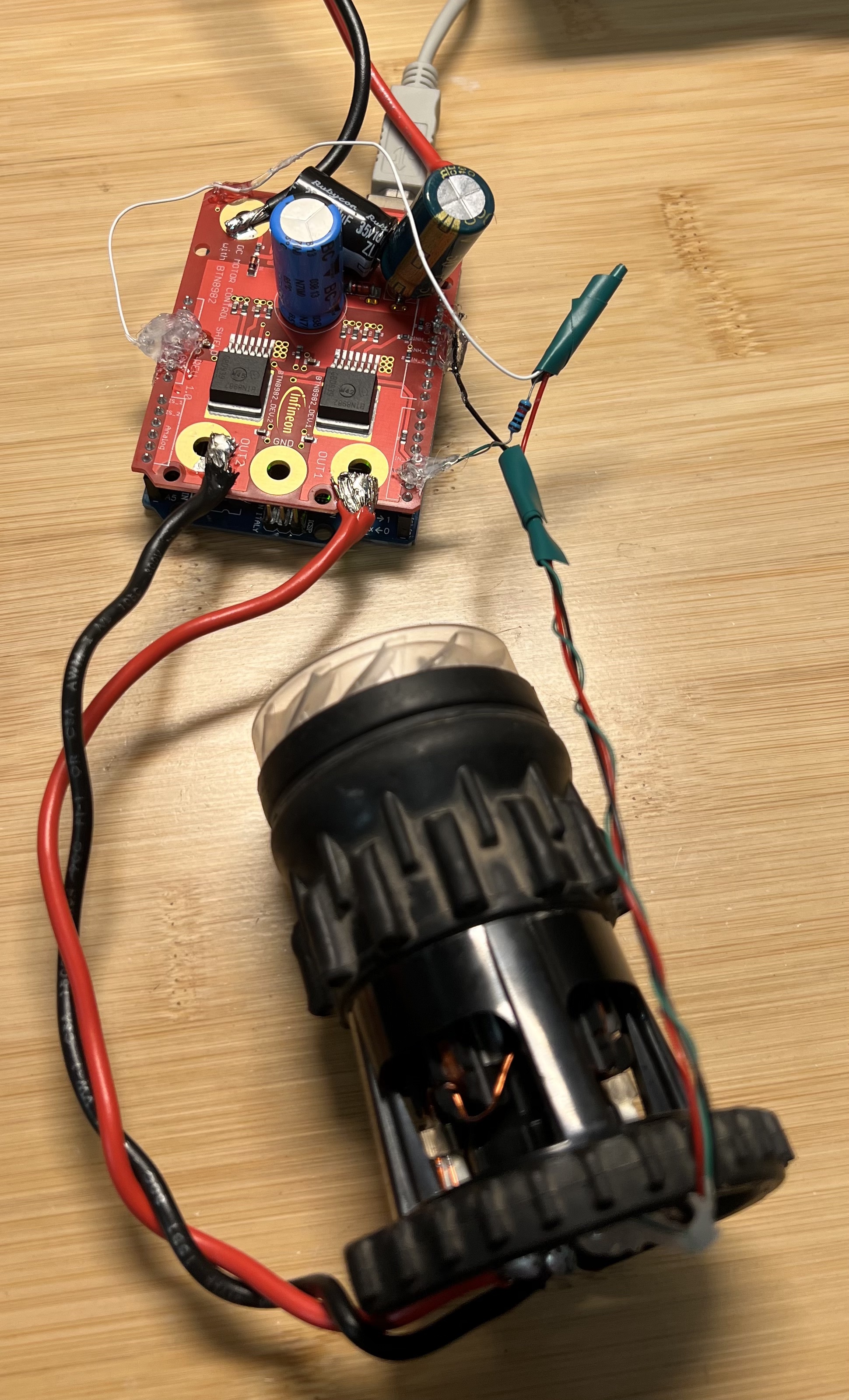
Dyson V10 Setup
Dyson handheld vacuum cleaners utilize high RPM brushless DC motors. Specifications indicate that some models can reach as high as 125000 RPM. I’ve disassembled DC56(V2), V6, and V10 models. Each has a brushless single-phase motor, with differing number of poles: two for the DC56, four for the V6, and eight for the V10. An earlier article about their DC56(V2) motor hinted that besides the mechanical design, the controlling software is the key. The electronics are relatively straightforward, including an H-bridge driver, microcontroller, and hall effect sensor. I’ve taken up the task and developed my own software to match Dyson’s factory performance. My software could potentially be used with all their brushless motors. The components I utilized include an Arduino Uno (8-bit ATmega328P microcontroller), H-bridge controller, and a hall effect sensor. Despite Dyson V10 employing a 32-bit ARM micro-controller, I managed to control it using an 8-bit Arduino, which is cheaper component.
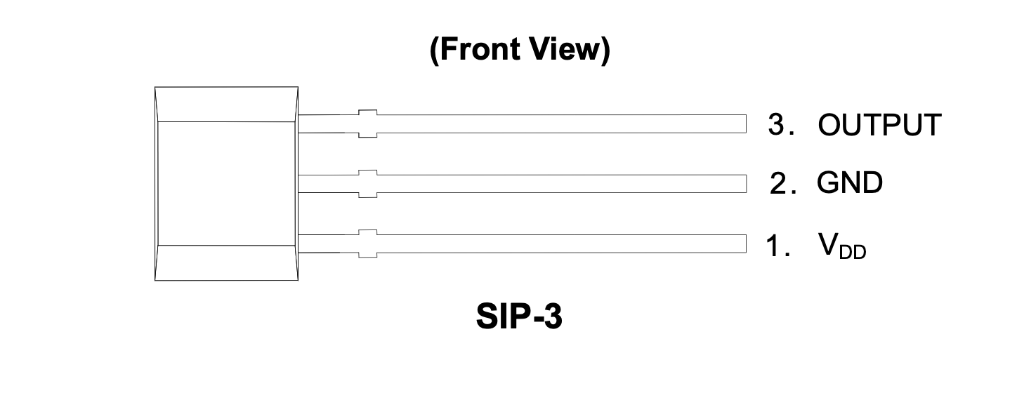
1. Hall Effect Sensor
I reused the hall effect sensor from the original control board, but it can also be sourced from retailers such as Digikey, Adafruit, or Sparkfun. This sensor requires a pull-up resistor (~5k ohm) at the output pin.
2. H-Bridge Driver
Several H-Bridge options are available on the market, but considering these beasts can consume ~500 watts, it’s preferable to choose robust ones. I bought H-Bridge with BTN8982TA from Digikey and BTS7960B 43A in Amazon. The former proved more reliable and also comes as an Arduino shield, making wiring simpler. The user manual for BTN8982TA board is here.
3. Powersupply
A power supply capable of delivering 25V at a minimum of 600 watts is necessary.
4. Control Software
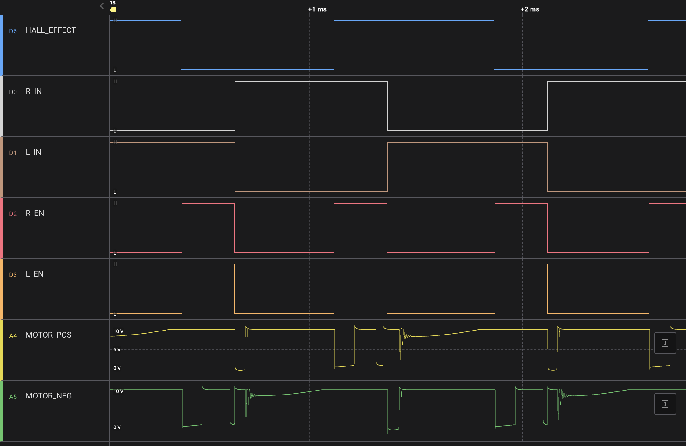
The software consists of one GPIO interrupt for the hall effect sensor and two timer interrupts for control loop and pulse length measurement. My initial approach was straightforward: each time the hall effect sensor detected a rising or falling edge, I switched the current direction on the H-bridge driver. This approach allowed me to achieve 60000 RPM with no issues, but higher RPMs were unattainable. Here is my scope capture of V6 motor with this approach.
Upon observing that enabling the H-bridge before the hall effect sensor’s rising/falling edge boosted speed, this is because the hall effect sensor’s location with respect to the coils. I introduced an adjustable time offset from the previous hall effect sensor edge and enabled H-bridge after this offset. The system remains a closed-loop controlled by the hall effect sensor, however the pulse width control loop is phase-shifted. Now, it is time to reduce pulse width to achieve higher RPMs. A new challenge emerged in getting the minimum pulse width, the timer interrupt service routine measuring pulse durations couldn’t be reduced after some point even when I set the minimum timer period. The problem was the Arduino library digitalWrite(.)/digitalRead(.) functions, which take tens of instruction cycles. I switched to direct GPIO port access to minimize latency in setting GPIOs.
Direct GPIO Port Access Compiled Assembly Code
  PORTD |= 0b00001000;
     4ae:       5b 9a           sbi     0x0b, 3 ; 11
Arduino Library digitalWrite(.) Compiled Assembly Code
void digitalWrite(uint8_t pin, uint8_t val)
{
        uint8_t timer = digitalPinToTimer(pin);
     476:       e5 e7           ldi     r30, 0x75       ; 117
     478:       f0 e0           ldi     r31, 0x00       ; 0
     47a:       84 91           lpm     r24, Z
        uint8_t bit = digitalPinToBitMask(pin);
     47c:       e1 eb           ldi     r30, 0xB1       ; 177
     47e:       f0 e0           ldi     r31, 0x00       ; 0
     480:       d4 91           lpm     r29, Z
        uint8_t port = digitalPinToPort(pin);
     482:       ed e9           ldi     r30, 0x9D       ; 157
     484:       f0 e0           ldi     r31, 0x00       ; 0
     486:       c4 91           lpm     r28, Z
        volatile uint8_t *out;

        if (port == NOT_A_PIN) return;
     488:       cc 23           and     r28, r28
     48a:       89 f0           breq    .+34            ; 0x4ae <_Z7forwardv+0x3c>

        // If the pin that support PWM output, we need to turn it off
        // before doing a digital write.
        if (timer != NOT_ON_TIMER) turnOffPWM(timer);
     48c:       81 11           cpse    r24, r1
     48e:       0e 94 8c 00     call    0x118   ; 0x118 <turnOffPWM>

        out = portOutputRegister(port);
     492:       ec 2f           mov     r30, r28
     494:       f0 e0           ldi     r31, 0x00       ; 0
     496:       ee 0f           add     r30, r30
     498:       ff 1f           adc     r31, r31
     49a:       ea 57           subi    r30, 0x7A       ; 122
     49c:       ff 4f           sbci    r31, 0xFF       ; 255
     49e:       a5 91           lpm     r26, Z+
     4a0:       b4 91           lpm     r27, Z

        uint8_t oldSREG = SREG;
     4a2:       8f b7           in      r24, 0x3f       ; 63
        cli();
     4a4:       f8 94           cli

        if (val == LOW) {
                *out &= ~bit;
        } else {
                *out |= bit;
     4a6:       ec 91           ld      r30, X
     4a8:       ed 2b           or      r30, r29
     4aa:       ec 93           st      X, r30
        }

        SREG = oldSREG;
     4ac:       8f bf           out     0x3f, r24       ; 63
}
Following phase shifting from the hall effect detections and GPIO setting optimization, I achieved between 90000 and 120000 RPM for the Dyson DC56(V2), V6, and V10 with the same efficiency as the original models. The Dyson V6 signal capture at 120000 RPM is shown below.
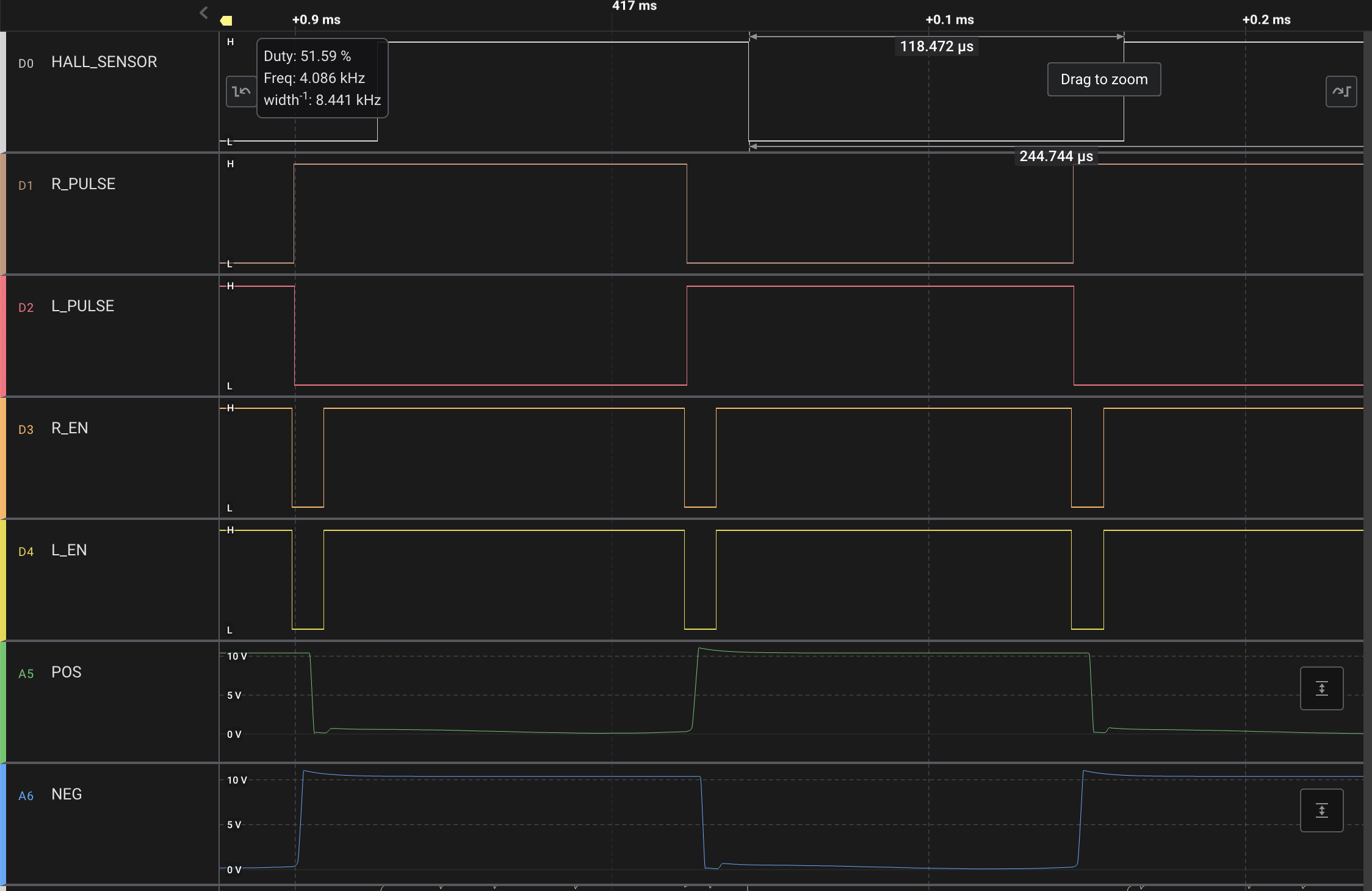
My code supports Dyson DC56(V2), V6, and V10 motors. The high-level control loop uses a fixed look-up table for RPM transitions, although it can be converted into a PI control loop.
Some Issues and Tips
- The V10 does not ramp-up as smoothly as the original Dyson V10, but the top RPM efficiency is equivalent.
- I recommend using a current limit during the development phase to protect your mosfets, though it will need to be removed to reach high RPMs.
- Avoid running the system excessively without proper cooling. The best cooling location is behind the motor, providing ample airflow. Position the H-bridge circuitry output of the airflow.
For up-to-date code, you can check the repo here.
#define HALL_EFFECT 2
// H-Bridge Arduino Shield with BTN8982TA
#define R_INH 12
#define L_INH 13
#define R_IN 3
#define L_IN 11
#define R_IS A0
#define L_IS A1
// CURRENT_LIMIT_ANALOG_COUNTER / 1023 * 5 * 19.5A = I_LIMIT
#define CURRENT_LIMIT_ANALOG_COUNTER 1000
#define ENABLE_CURRENT_LIMIT_CHECK false
#define REF_CYCLE_FROM_DISABLE_TO_ENABLE 8
// #define DYSON_V2
// #define DYSON_V6
#define DYSON_V10
void disable_driver()
{
// digitalWrite(R_INH, 0);
// digitalWrite(L_INH, 0);
PORTB &= 0b11001111;
}
void enable_driver()
{
// digitalWrite(R_INH, 1);
// digitalWrite(L_INH, 1);
PORTB |= 0b00110000;
}
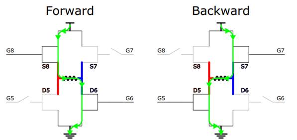
void forward()
{
// digitalWrite(R_IN, 1);
// digitalWrite(L_IN, 0);
PORTD |= 0b00001000;
PORTB &= 0b11110111;
}
void reverse()
{
// digitalWrite(R_IN, 0);
// digitalWrite(L_IN, 1);
PORTD &= 0b11110111;
PORTB |= 0b00001000;
}
void head_start()
{
// Poking
reverse();
delayMicroseconds(4000);
forward();
delayMicroseconds(4000);
for (int i = 0; i < 10; i++)
{
if (digitalRead(HALL_EFFECT))
{
reverse();
}
else
{
forward();
}
delayMicroseconds(500);
}
}
#define FIRST_STATE 0
const uint8_t early_pulse_cycles[]
{
#ifdef DYSON_V10
0,
0,
0,
0,
0,
0,
REF_CYCLE_FROM_DISABLE_TO_ENABLE,
REF_CYCLE_FROM_DISABLE_TO_ENABLE,
REF_CYCLE_FROM_DISABLE_TO_ENABLE - 2,
REF_CYCLE_FROM_DISABLE_TO_ENABLE - 2,
REF_CYCLE_FROM_DISABLE_TO_ENABLE - 2,
REF_CYCLE_FROM_DISABLE_TO_ENABLE - 3,
REF_CYCLE_FROM_DISABLE_TO_ENABLE - 4,
#elif defined(DYSON_V6)
0,
0,
0,
REF_CYCLE_FROM_DISABLE_TO_ENABLE - 3,
REF_CYCLE_FROM_DISABLE_TO_ENABLE - 4,
REF_CYCLE_FROM_DISABLE_TO_ENABLE - 5,
#elif defined(DYSON_V2)
0,
0,
0,
REF_CYCLE_FROM_DISABLE_TO_ENABLE - 4,
REF_CYCLE_FROM_DISABLE_TO_ENABLE - 4,
#endif
};
const uint8_t pulse_cycle_arr[]
{
#ifdef DYSON_V10
170,
130,
60,
42,
24,
15,
13,
10,
6,
3,
1,
1,
1,
#elif defined(DYSON_V6)
150,
42,
24,
19,
13,
9,
#elif defined(DYSON_V2)
100,
45,
34,
25,
25,
#endif
};
const float rpm_thresholds[][2]
{
#ifdef DYSON_V10
{ 0.f, 300.f},
{ 700.f, 1200.f},
{ 2000.f, 5000.f},
{ 3750.f, 7500.f},
{ 5000.f, 14000.f},
{12000.f, 20000.f},
{22000.f, 30000.f},
{25000.f, 40000.f},
{35000.f, 50000.f},
{45000.f, 70000.f},
{60000.f, 85000.f},
{70000.f, 90000.f},
{70000.f, 140000.f},
#elif defined(DYSON_V6)
{0.f, 10000.f},
{7500.f, 15000.f},
{10000.f, 35000.f},
{30000.f, 65000.f},
{60000.f, 80000.f},
{70000.f, 140000.f},
#elif defined(DYSON_V2)
{0.f, 20000.f},
{15000.f, 30000.f},
{20000.f, 70000.f},
{60000.f, 100000.f},
{80000.f, 150000.f}
#endif
};
volatile uint8_t state = FIRST_STATE;
volatile float speed = 0.f; // in RPM
volatile bool hall_value = false;
volatile bool early_pulse_enable = false;
volatile uint8_t forward_cnt = 0;
volatile uint8_t reverse_cnt = 0;
volatile uint8_t forward_cnt_happenned = 0;
volatile uint8_t reverse_cnt_happenned = 0;
volatile uint8_t inhibit_cnt_forward = 0;
volatile uint8_t inhibit_cnt_reverse = 0;
volatile uint8_t pulse_duration;
volatile uint8_t early_pulse_cnt_from_inhibit;
volatile uint8_t disable_to_hall_effect;
volatile unsigned long time_rising = 0;
volatile unsigned long time_falling = 0;
volatile unsigned long delta_time_high = 0;
volatile unsigned long delta_time_low = 0;
void hall_effect_int()
{
if (!early_pulse_enable)
{
enable_driver();
}
// hall_value = digitalRead(HALL_EFFECT);
hall_value = (PIND & 0b00000100);
if (hall_value)
{
time_rising = micros();
delta_time_high = time_rising - time_falling;
forward_cnt_happenned = forward_cnt;
forward_cnt = 0;
inhibit_cnt_forward = 0;
}
else
{
time_falling = micros();
delta_time_low = time_falling - time_rising;
reverse_cnt_happenned = reverse_cnt;
reverse_cnt = 0;
inhibit_cnt_reverse = 0;
// Measures number of cycles between driver-off and hall effect sensor change
disable_to_hall_effect = inhibit_cnt_forward;
}
}
ISR(TIMER1_COMPA_vect){
TCNT1 = 0; // Clear for every interrupt
if (hall_value)
{
if (forward_cnt >= pulse_duration)
{
if (inhibit_cnt_forward == 0)
{
disable_driver();
reverse();
}
inhibit_cnt_forward++;
}
else
{
forward_cnt++;
}
if (early_pulse_enable)
{
if (inhibit_cnt_forward == early_pulse_cnt_from_inhibit)
{
enable_driver();
}
}
}
else
{
if (reverse_cnt >= pulse_duration)
{
if (inhibit_cnt_reverse == 0)
{
disable_driver();
forward();
}
inhibit_cnt_reverse++;
}
else
{
reverse_cnt++;
}
if (early_pulse_enable)
{
if (inhibit_cnt_reverse == early_pulse_cnt_from_inhibit)
{
enable_driver();
}
}
}
}
volatile uint8_t cnt = 0;
ISR(TIMER2_COMPA_vect){
TCNT2 = 0; // Clear for every interrupt
if (++cnt >= 25) // 25 * 10ms = 250ms
{
cnt = 0;
if (speed > rpm_thresholds[state][1])
{
state++;
}
if (speed < rpm_thresholds[state][0])
{
state--;
}
// Update pulse control parameters
pulse_duration = pulse_cycle_arr[state];
early_pulse_cnt_from_inhibit = early_pulse_cycles[state];
early_pulse_enable = early_pulse_cycles[state] != 0;
}
}
void setup()
{
Serial.begin(115200);
pinMode(HALL_EFFECT, INPUT);
pinMode(HALL_EFFECT, INPUT_PULLUP);
pinMode(R_IS, INPUT);
pinMode(L_IS, INPUT);
pinMode(R_INH, OUTPUT);
pinMode(L_INH, OUTPUT);
pinMode(R_IN, OUTPUT);
pinMode(L_IN, OUTPUT);
disable_driver();
cli();
attachInterrupt(digitalPinToInterrupt(HALL_EFFECT), hall_effect_int, CHANGE);
// Timer 1
TCCR1A = 0; // Reset entire TCCR1A to 0
TCCR1B = 0; // Reset entire TCCR1B to 0
TCNT1 = 0; // Clear timer1 counter
// Compare A
TCCR1B |= B00000010; // CS12 CS11 CS10 -> 010 -> CLK / 8
TIMSK1 |= B00000010; // Set OCIE1A 1 -> compare match for A
OCR1A = 12; // 16 MHz / 8 / 12 -> 6us
// Timer 2
TCCR2A = 0; // Reset entire TCCR2A to 0
TCCR2B = 0; // Reset entire TCCR2B to 0
// Compare A
TCCR2B |= B00000101; // CS12 CS11 CS10 -> 101 -> CLK / 1024
TIMSK2 |= B00000010; //Set OCIE1A to 1 -> compare match for A
OCR2A = 157; // 16 MHz / 1024 / 157 -> ~10 ms
enable_driver();
head_start();
// Initial condition setup
state = FIRST_STATE;
pulse_duration = pulse_cycle_arr[FIRST_STATE];
early_pulse_cnt_from_inhibit = early_pulse_cycles[FIRST_STATE];
early_pulse_enable = early_pulse_cycles[FIRST_STATE] != 0;
sei(); // Enable back the interrupts
}
void loop()
{
float period_time = (float)(delta_time_high + delta_time_low);
#ifdef DYSON_V10 // 8 poles, single phase
speed = (period_time != 0.f) ? (15.f * 1000000.f / period_time) : 0.f;
#elif defined(DYSON_V6) // 4 poles, single phase
speed = (period_time != 0.f) ? (30.f * 1000000.f / period_time) : 0.f;
#elif defined(DYSON_V2) // 2 poles, single phase
speed = (period_time != 0.f) ? (60.f * 1000000.f / period_time) : 0.f;
#endif
// These are custom inputs for debugging
if (Serial.available())
{
char data = Serial.read();
if (data == 'a')
{
pulse_duration++;
}
if (data == 'z')
{
pulse_duration--;
}
if (data == 'w')
{
early_pulse_cnt_from_inhibit++;
}
if (data == 'q')
{
early_pulse_cnt_from_inhibit--;
}
if (data == 'e')
{
early_pulse_enable = true;
}
if (data == 's')
{
cli();
disable_driver();
}
}
int is_r = analogRead(R_IS);
int is_l = analogRead(L_IS);
if (ENABLE_CURRENT_LIMIT_CHECK && ((is_r > CURRENT_LIMIT_ANALOG_COUNTER) || (is_l > CURRENT_LIMIT_ANALOG_COUNTER)))
{
cli();
disable_driver();
}
Serial.print(" speed: ");
Serial.print(speed);
Serial.print(" RPM");
Serial.print(" state: ");
Serial.println(state);
// Serial.print("high: ");
// Serial.print(delta_time_high);
// Serial.print(" low: ");
// Serial.print(delta_time_low);
// Serial.print(" forward_cnt: ");
// Serial.print(forward_cnt_happenned);
// Serial.print(" reverse_cnt: ");
// Serial.print(reverse_cnt_happenned);
// Serial.print(" disable_to_hall_effect: ");
// Serial.print(disable_to_hall_effect);
// Serial.print(" is_r: ");
// Serial.print(is_r);
// Serial.print(" is_l: ");
// Serial.print(is_l);
// Serial.print(" pulse_duration: ");
// Serial.print(pulse_duration);
// Serial.print(" early_pulse_enable: ");
// Serial.print(early_pulse_enable);
// Serial.print(" early_pulse_cnt_from_inhibit: ");
// Serial.println(early_pulse_cnt_from_inhibit);
}